There's nothing quite as frightening as someone who knows they are right. ~Michael Faraday
Synchronizing and Synchronizing Equipment


Solar Capacity
Wind Capacity
Solar Star
Mojave Wind Farm


Luddington Pumped Storage
(Northwest Michigan) Six Turbines can operate as pumps or generators. Once upgrades are completed generator capacity close to 2,300 MW.

Highland Wind Farm
Has 218 2.3 MW wind turbines (502 MW total). It is located in the northwest corner of Iowa and is in the MEC LBA (Local Balancing Authority) area.

Mackinac HVDC
This 200 MW voltage sourced HVDC converter connects the upper & lower peninsulas of Michigan.
1. Synchronizing and Synchronizing Equipment
1.1 Theory of Synchronizing
When closing a circuit breaker between two energized parts of the power system, it is crucial to match voltages on both sides of the circuit breaker before closing. If this matching or "synchronizing" process is not done correctly, a power system disturbance will result and equipment (including generators) can be damaged. In order to synchronize properly, three different aspects of the voltage across the circuit breaker must be closely monitored. The three aspects of the voltage are called the synchronizing variables and are:
- 1. The voltage magnitudes
- 2. The frequency of the voltages
- 3. The phase angle difference between the voltages
1.1.1 Voltage Magnitude Synchronizing Variable
If the voltage magnitudes are not closely matched, a sudden rise in Mvar flow will appear across the circuit breaker as it is closed. For example, if a 345 kV circuit breaker were closed with a 20 kV difference in voltage across the open circuit breaker, a large Mvar flow would suddenly occur upon closing. The allowable voltage magnitude differences across the open circuit breaker are system specific. However, for general guidance, a difference of a few percent is unlikely to cause any serious problem.
1.1.2 Frequency Synchronizing Variable
If the frequencies on either side of an open circuit breaker are not matched prior to closing, a sudden change in MW flow will appear across the circuit breaker as it is closed. The sudden MW flow change is in response to the initial frequency difference as the system seeks to establish a common frequency once the circuit breaker is closed. The allowable frequency difference is again system specific. However, a general guideline would be to have the frequencies within 0.1 Hz of each other prior to closing.
1.1.3 Phase Angle Synchronizing Variable
The third synchronizing variable - and likely the most important of the three - is the voltage phase angle difference. If the phase difference between the voltages on either side of the open circuit breaker is not reduced to a small value, a large MW flow increase will suddenly occur once the circuit breaker is closed. The voltage phase angle difference is the difference between the zero crossings of the voltages on either side of the open circuit breaker. Ideally, the voltage phase angle should be as close to zero degrees as possible before closing the circuit breaker.
1.2 Synchronizing Examples
The importance of synchronizing cannot be overstated. All system operators should understand the theory and practice of synchronizing. If two power systems are synchronized via an open circuit breaker, and the synchronizing process is not done correctly, generators can be severely damaged. Two scenarios for synchronizing follow to further describe the synchronizing process.
1.2.1 Scenario #1: Synchronizing Two Islands
The first scenario assumes that two islands are about to be connected together using the open circuit breaker as illustrated in Figure 1. The two islands, since they are independent electrical systems, will have different frequencies so all three of the synchronizing variables must be monitored to ensure they are within acceptable limits prior to closing the open circuit breaker.
The system operators for the two islands will likely have to adjust generator MW output levels (or adjust island load magnitudes) in one or both islands to achieve the desired adjustment in frequencies and phase angles. Voltage control equipment (reactors, capacitors, etc.) may also be used as necessary to change voltage magnitudes to within acceptable levels.
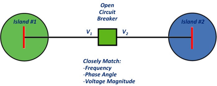
Figure 1
Synchronizing Two Islands
1.2.2 Scenario #2: Establishing the Second Tie
Once the first transmission line is closed interconnecting the two islands, the frequency will be the same in the two areas. Therefore, one of the three synchronizing variables (the frequency) is no longer a factor. However, as illustrated in Figure 2, the other two synchronizing variables must still be monitored. Generation and/or voltage control equipment may be to be utilized to ensure the phase angle and voltage magnitude differences are within acceptable limits prior to closing the second circuit breaker. This process should be easier than closing the first transmission line (Scenario #1) as frequency is no longer a factor.
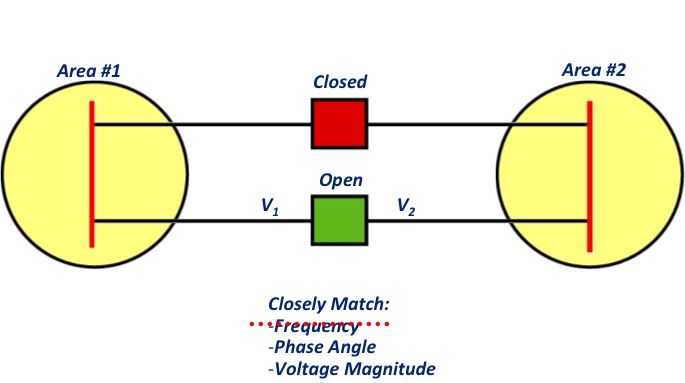
Figure 2
Establishing the Second Transmission Tie
1.3 Synchronizing Equipment
1.3.1 Synchroscope
A synchroscope is a simple piece of equipment that is used to monitor the three synchronizing variables. A basic synchroscope (illustrated in Figure 3) inputs voltage waveforms from the two sides of the open circuit breaker. If the voltage waveforms are at the same frequency, the synchroscope does not rotate. If the voltage waveforms are at a different frequency, the synchroscope rotates in proportion to the frequency difference. The synchroscope needle always points to the voltage phase angle difference.
A synchroscope is a manual device in that an operator must be watching the "scope" to ensure they close the circuit breaker at the correct time. The synchroscope is normally mounted above eye level on a "synch panel". The synch panel also contains two voltmeters so that the voltage magnitudes can be simultaneously compared.
The synchroscope in Figure 3 reflects a slight voltage magnitude mismatch, and a stationary synchroscope with a phase angle of approximately 35°. The fact that the synchroscope needle is not rotating indicates frequency is the same on either side of the circuit breaker.
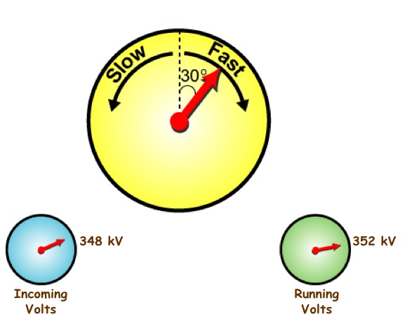
Figure 3
Synchroscope in a Synch Panel
1.3.2 Synchro-Check Relays
A synchro-check or synch-check relay electrically determines if the difference in voltage magnitude, frequency and phase angle falls within allowable limits. The allowable limits will vary with the location on the power system. Typically, the further away from generation and load, the more phase angle difference can be tolerated. Synch-check relays typically do not provide indication of the voltage magnitude, frequency or phase angle. A synch-check relay decides internally whether its conditions for closing are satisfied. The synch-check relay will either allow or prevent closing depending on its settings. A typical synch-check relay may allow closing if the voltage angle across the breaker is less than 30°.
1.3.3 Application of Synchronizing Equipment
At power plants, synchroscopes are routinely installed to permit manual closing of a circuit breaker. In addition, synch-check relays can be used to "supervise" the closing of the circuit breaker and prevent distracted or inexperienced operator from initiating a bad close.
Modern power plants typically utilize automatic synchronizers. Automatic synchronizers send pulses to the generator exciter and governor to change the voltage and frequency of the unit. The synchronizer will automatically close the breaker when it is within an allowable window.
Substations on the transmission system have traditionally had synchroscopes installed. However, few substations are now manned due to the availability of powerful SCADA systems. Because of this development, newer substations may or may not have a synch panel, depending on the transmission company procedures. Since most circuit breaker operations are done remotely, transmission companies often rely on synch-check relays to supervise closing of breakers.
Figure 4 illustrates a possible synchronizing system for substation breakers. Note the use of a synch scope and a synch-check relay. Electrical contacts can be opened or closed to rearrange the synchronizing system as desired.
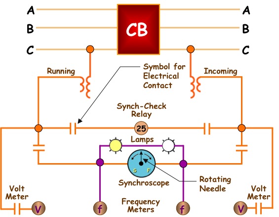
Figure 4
Synchronizing System for a Substation Breaker